![]() Autonomous 3D Map Generation from Aerial Photography
Autonomous 3D Map Generation from Aerial Photography
Executive Summary
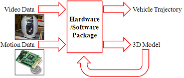 A three dimensional terrain map may be generated by combining the information measured from video and motion sensors. While aerial observations have long been a key to situational awareness in military environments, search and rescue missions, and urban planning, these observations usually arrive in the cumbersome format of a large pile of two dimensional still frames. Each still frame provides a flattened perspective of the 3D terrain, but only for the moment in time in which that portion of the world is visible. By creating a 3D map, civil engineers, architects, military planners, robotic platforms, and rescue organizers could quickly and effectively understand the lay of the land to direct their missions.
For implementation on an aerial vehicle (whether remotely operated or autonomous), special care must be given to ensure the integrity of the data collected. Six highly dynamic degrees of freedom must be monitored for position and orientation calculations for the map generation algorithm. Additionally, the GPS-aimable camera rotations must be measured to gather valuable information to compare the camera trajectory with the vehicle trajectory.
Primary Project Objectives
- Configure the instruments for data capture, telemetry, and recording
- Integrate hardware with the aircraft
- Prepare data for existing reconstruction algorithms
- Fly!
Research Description
The artistic rendering in the right pane of the figure below depicts the blending of several consecutive video frames, blurred by the forward motion of the vehicle driving down the highway. Psychological experiments seem to indicate that a large portion of 3D perception in humans is derived from monocular processes such as moving through an environment rather than stereovision performed from a static position and orientation.
It is feasible for a single camera to gather enough information to reconstruct a three-dimensional scene.
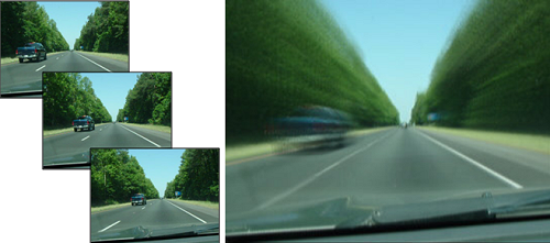
[Above] Effect of Motion on Percieved Vision
New advances in computer vision have enabled researchers to successfully determine the structure of the 3D environment from a sequence of images. Each experiment and publication furthers the potential of robotic platforms in their sensing and processing capabilities. The goal is situational awareness for the autonomous vehicles – that they might have an “appreciation” for the 3D world in which they move, measure, and manipulate.
This particular research seeks to prepare existing algorithms for implementation aboard an aerial vehicle. The potential of autonomous 3D map generation will be magnified by the vast areas of terrain which can be observed from a single flight. Yet aerial photography introduces a number of new challenges. Aircraft rapidly change position and orientation as they roll, pitch, and yaw about their domain, cruising at speeds that vary depending upon the current task.
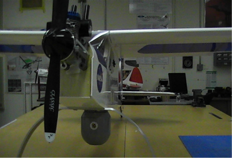
[Above] Data Collection Platform. Puller Prop. Wingspan 8ft.
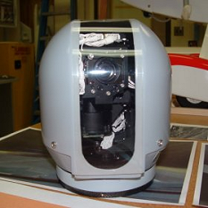
To capture the aerial photography, the pictured aircraft will be remotely piloted with the gyro-stabilized camera mounted to the nose of the plane. The aircraft will be fitted with special hardware to measure the motions of the aircraft, record data over time, and broadcast needed information to the ground. The camera is a highly sophisticated piece of equipment. It is gyro-stabilized to provide a clear picture despite turbulence in the air and mechanical vibrations in the aircraft. This camera is GPS-enabled. The ground station can direct the camera to focus its attention at an object on the ground with coordinates. The camera will stay trained on the object, collecting more and more information from an array of perspectives. This will be essential to developing the 3D model of the observed object as well as the surrounding terrain.
 When the data is retrieved, it must be transformed into a format that is acceptable for current computer vision algorithms. The camera rotations about its azimuth and elevation axes will be recorded and compared to the estimated vehicle trajectory measured by magnetometers, GPS, and an inertial measurements unit. All of these positions and orientations are estimates to be refined by the computation of the video imagery corresponding with each fly-by, each banked turn, each landing. Most importantly, at Morpheus Lab, we fly. This aircraft will be an impressive data collection platform.
[Above Left] Gyro-Stabilized, GPS-Enabled, Directable
Video Camera - Controp Precision Technologies
 [Below Left] MicroPilot Hardware Test.
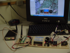
In order to control the aircraft and direct the orientation of the gimbaled camera, an advance autopilot is needed. MicroPilot's MP 2128g integrates information from GPS signals, onboard accelerometers and rate gyroscopes, a 3D magnetometer (compass), and an ultrasonic altimeter to accurately estimate the position of the aerial data collection platform. The system pictured has been upgraded with a radio modem from MicroHard Systems, Inc. to transmit telemetry to a ground station for data collection and to deliver commands from the ground station to the aircraft's autopilot. The commands may include GPS coordinates for the gimbaled camera to track. Pictured is the MP 2128g in a portable test stand while performing tests on data transmission.
Current Progress Updates
[February 2009]
The project’s success depends on the collective efforts of three main hardware suites:
1. The Controp D-STAMP gimbaled camera
2. The MicroPilot 2128g autopilot computer
3. The IftronTech 5.8 GHz Stinger video transmission system
After much hard work, the Controp D-STAMP gimbaled camera has finally been powered on. It operates its startup bit sequence on initialization and waits for commands to be sent. The following figure shows the camera and the related hardware in their current configuration as well as a screenshot taken from the camera’s onboard processor.
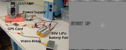
[Above] Controp D-STAMP Hardware Configuration & Screenshot
This gimbaled camera is a high-fidelity system, ready to stabilize video feeds while aiming the camera in a desired orientation. Commands sent to the D-STAMP may be in the form of low level servo requests or as high level tracking sequences where the camera will continuously adjust its orientation to stay fixed on a set GPS location as the base of the camera is moving. This latter ability will prove very useful when the camera is finally integrated onboard the flight platform.
[September 2008]
Video processing to construct the 3D map is to be done by a computer at a ground station. This will allow potential users to access the map as it is generated in real time, rather than requiring them to wait for the aircraft to land before uploading the valuable video data. This method gives rise to two powerful strengths of the proposed map building system to potential users: (1) vehicle survival is not critical to mission success and (2) multiple vehicles may be used to generate a single comprehensive map of the terrain.
With the video recording equipment and the video processing equipment separated, a reliable video transmission system is required. Iftron Technologies was selected to provide such a system to transmit and receive full, 640x480 resolution video at 30 frames per second. The 5.8 GHz band was selected rather than the 2.4 GHz band to deliver a clean video signal, helping to mitigate video distortion from possible interference of existing 2.4 GHz signals, including the remote control transmission and the transmission and reception of the MicroPilot MP 2128g autopilot.
When successful video transmission from a static camera in confirmed with the Iftron Technologies system in live tests aboard the aerial testing apparatus, the system will be integrated to instead transmit video from the gyro-stabilized, GPS-enabled, directable video D-STAMP camera from Controp Precision Technologies.
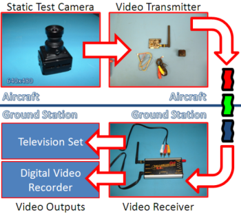
[Above] Iftron Technologies Video System
![]()

