
![]() Electroactive Polymer Synthetic Jet Actuators
("EJETs")
Electroactive Polymer Synthetic Jet Actuators
("EJETs")
for Low Speed Active Flow Control
Executive Summary
 The multidisciplinary field of active flow control holds
the promise of significantly increasing the aerodynamic efficiency of vehicles, thereby directly reducing the operating costs and environmental impacts of vehicles without needing to modify or compromise vehicle design.
One means of achieving active flow control utilizes synthetic jets (SJs), which work by injecting
energy into fluid flow fields through the cyclic transfer of fluid momentum. The objective of
this ongoing research is to develop and characterize a SJ actuation method utilizing electroactive
polymers that meets four critical requirements for implementation:
The multidisciplinary field of active flow control holds
the promise of significantly increasing the aerodynamic efficiency of vehicles, thereby directly reducing the operating costs and environmental impacts of vehicles without needing to modify or compromise vehicle design.
One means of achieving active flow control utilizes synthetic jets (SJs), which work by injecting
energy into fluid flow fields through the cyclic transfer of fluid momentum. The objective of
this ongoing research is to develop and characterize a SJ actuation method utilizing electroactive
polymers that meets four critical requirements for implementation:
- that it is inexpensive,
- that it is lightweight,
- that it is mechanically simple, and
- that it operates efficiently in low speed regimes (i.e. < 200 knots).
The actuation method utilizes a pre-strained ~100 micron thick dielectric elastomer membrane excited to operate at resonance by the periodic application of Maxwell stress introduced through compliant electrodes. Experimental results to date have demonstrated greater than +/-25 m/s cyclic velocity at the synthetic jet exit with an actuation frequency of approximately 200 Hertz, a maximum power consumption of 0.5 Watts RMS per actuator, a mass less than 10 grams, and a nozzle area of 1.6 square centimeters.
Primary Project Objectives
- Devise an inexpensive, lightweight, and efficient means of actuating a synthetic jet using a class of high displacement, low blocked-force electroactive polymers known as dielectric elastomers.
- Perform a parametric study of the device using both experimental and computer modeling techniques to establish design parameters so that a device may be engineered to meet specific end user requirements.
- Construct and characterize an engineered device under closed loop control
Research Description
For more than a decade, significant effort has been applied to studying and developing synthetic jet actuators for active flow control applications. Forcing factors influencing this effort include increasingly stringent demands for reducing vehicle emissions, reducing vehicle acoustic loads, and reducing vehicle drag while at the same time increasing vehicle capabilities such as cargo capacities, aircraft STOL capabilities, endurance, and range. Aircraft, automobiles, ships, and submarines all represent potential areas of application for active flow control devices generally, and synthetic jet actuators in particular.
Flow control, broadly defined, refers to the intentional manipulation of a flow field to induce desired flow phenomena in the presence of specific flow conditions. This may include passive or active flow control, where passive control solutions are typically aimed at a narrow design point (e.g. cruise speed), and active flow control solutions tend to be more broadband in terms of applicability. Active control implies some adaptability in how and when a given solution is to be applied, which thus adds a requirement for a feedback mechanism and control algorithm for implementation.
Synthetic jets are most often described in terms of two functional parameters:
- frequency of operation, and
- induced velocity at the nozzle exit
Two equations are used most often to relate these functional parameters to potential flow control applications. The first such equation relates the so-called momentum coefficient, which is given by:
where p and pj are the free-stream and jet fluid densities, Uj is the averaged jet velocity at the nozzle exit, U is the free-stream velocity, c is an application-specific geometric parameter describing a characteristic length to be influenced by the synthetic jet (e.g. wing chord length), and b is a geometric parameter describing the actuator geometry, typically width or diameter of the actuator’s nozzle. For adequate control authority in flow separation control applications the momentum coefficient must be, at a minimum, on the order of 10e-3. The second archetypal equation used to relate synthetic jet performance applicability is the nondimensional frequency parameter, which is given by:
where fj is the frequency at which the synthetic jet is actuated, and the other variables represent the same parameters as in the equation for the momentum coefficient.
Understanding the relationship between actuation frequency and induced jet velocity is critical to understanding how a given synthetic jet actuator may be used in a real application. Thus the motivation for a study of membrane modal correlation with device performance is clear given that velocity performance of the E-JET has been determined to be highly dependent on membrane dynamics, in particular mode shape, which is in turn highly frequency dependent.
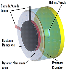
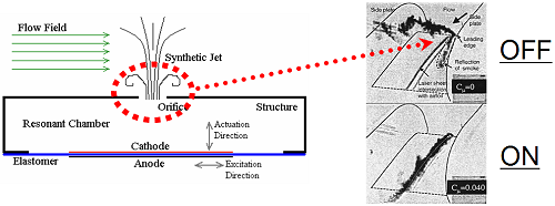
The fundamental principle that is applied in creating a synthetic jet is that of the vibrating, or resonating, membrane. The membrane is used to seal off one end of a chamber, while the other end is left partially open. The opening is referred to as the nozzle of the synthetic jet. When the membrane vibrates periodically it also alters the enclosed volume of the chamber, which in turn induces a flow into and out of the nozzle. The fluctuating velocity at the nozzle exit can be used to actively influence a surrounding fluid system (e.g. a flow field). This basic function is illustrated in the figure below. The images at the right show two cases for a wing at a high angle of attack to oncoming flow: 1) with the jet turned off, and 2) with the jet turned on. The flow is moving from the top right to the bottom left in the images. The synthetic jet nozzle is flush with the wing surface, and is located just behind the leading edge. In the image with the synthetic jet turned off, the indicator smoke (dark black) shows significant separation of the flow beginning at the leading edge. The image with the synthetic jet turned on to its maximum velocity shows nearly fully reattached flow.
In order to vibrate the membrane, E-JETs take advantage of a simple compliant capacitor actuation principle. A strong electric field is applied across the membrane thickness (~100 micron thickness) through compliant electrodes applied to opposing membrane surfaces. One side of the membrane carries the positive potential, and the other side remains at ground. Applying a strong electric field (on the order of 10MV per meter of membrane thickness) induces a pressure across the membrane thickness, known as Maxwell stress. This pressure acts to compress the membrane in the thickness direction in the area sandwiched by the electrodes.
Since the elastomer used has a Poisson’s ratio very close to ½, it may be considered incompressible, and thus the volume of the membrane remains constant under the application of pressure by the electrodes. Induced pressure in the membrane thickness direction decreases the membrane thickness, resulting in an expansion of the membrane area sandwiched by the electrodes. By simultaneously increasing the area of the membrane and reducing its thickness, the effective stiffness of the membrane is thus locally reduced in the area covered by the electrodes. Due to an applied membrane pre-strain, the membrane is biased to expand in the x-y plane orthogonal to the applied electric field (z). This relationship is shown in the following movie. The voltage is being applied at a low frequency (~2 Hz), and the expanding of the electrode coated area (black circle) can clearly be seen.
|
QuickTime Format. or try a different browser. Quicktime Player required for viewing. |
|
When the electric field is applied at a resonant frequency of the membrane, a significant vibratory response is induced through inertial coupling with the time-varying membrane stiffness. By sweeping through a range of frequencies identified as significant, the frequency response characteristics of the membrane-chamber-nozzle system may be identified. The movie below shows a short segment of a frequency sweep. Note in the movie the large number of modes observed. This behavior, called high modal density, is also commonly found in large space structures. The movie below was filmed at high speed in order to slow down the membrane dynamics enough to be observed with the unaided eye.
|
QuickTime Format. or try a different browser. Quicktime Player required for viewing. |
|
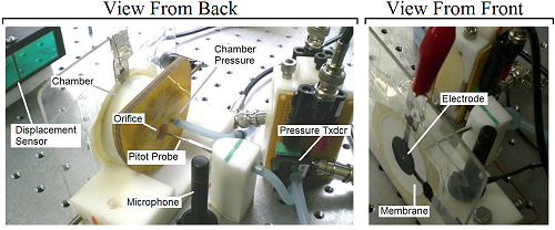
Data is also collected during these tests in order to determine how well the device is performing. Six performance metrics are collected:
- membrane displacement (at a single point),
- induced jet velocity,
- induced pressure inside the chamber,
- input voltage signal,
- input current drawn, and
- auditory signature.
The test setup is shown in the figure below:
A typical device response is shown in the figure below. The membrane mode shapes (shown to the right) are labeled on the plots to show at what frequencies they are detected. Note that three higher order mode s hapes are repeated at harmonic intervals in the excitation frequency. Obviously, the vibrational frequency of the membrane remains the same for each repeated mode shape, however, the higher excitation frequencies do represent a higher energy input the system and so higher vibrational amplitudes are observed. Note also that the membrane mode at which the best exit dynamic pressure (velocity) is observed is non-classical, and so its diagram is represented by a laser vibrometer scan image. The membrane mode shape at which best performance is attained is referred to as the “jet mode.”
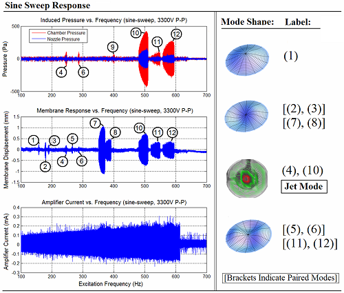
Note that membrane modes that are perfectly symmetric about the diameter, or diameters, of the membrane are not expected to give any induced volume change to the chamber due to the fact that the sum of their displacement fields would be zero at any given point in time. To illustrate this, note in the figure above the disparity between the high displacement magnitudes for numbers (7) & (8) and the negligible induced pressures inside the chamber and at the nozzle exit.
Normally, we would expect the first membrane mode shape to give the best performance due to its high net displacement. However, for these low blocked-force elastomers, the first membrane mode does not have enough power to move air efficiently.
It is the non-classical nature of the “jet mode” and its presence at a higher energy state that allows it to induce any significant velocity at all. The “jet mode” has been shown to be highly coupled with the chamber fluid dynamics. The movie below shows what the jet mode looks like slowed down to be viewed by the unaided eye.
|
QuickTime Format. or try a different browser. Quicktime Player required for viewing. You can download a free player HERE |
|
The basic characteristics of the device as tested are as follows:
- Lightweight device (< 10grams)
- Low power (~0.3 Watt/device)
- Induced velocities > 25m/s
- Low frequency of operation (~200 Hz)
- 5cm diameter by 2cm long chamber
- 1.3cm diameter by 0.5cm long nozzle
- 5cm diameter by ~0.1 mm thick membrane
- Membrane vibration is typically 1-5mm P-P
![]()